
Matthew Milburn
This presentation focuses on the design and development of a consumer grade telescopic wind turbine. The research on this topic stems from the author’s/presenter’s great interest in renewable energy. Having the belief that we need to make the generation of renewable energies more accessible and relevant to the average consumer. There is going to be the construction of a physical prototype that will serve as a base for further development using Computer Aided Design (CAD) software. The digital model will be evaluated through use of a simulation software in order to find working efficiencies. Generated data will be used to calculate a simulated power output. In the event of a successful model, the prototype will be subjected to a field test. A comparison of these results will be made, and conclusions will be drawn to determine possible applications and future points of development. It is believed that the wind turbine will generate a small amount of energy, however there is a possibility for this design to be adapted into a large-scale wind turbine in future years which may yield more significant results.

Matthew Milburn
Types of Wind Turbines
The field of wind energy is vast and new designs of wind turbines are produced every year. There is, however, two main groupings of wind turbines: Horizontal Axis Wind Turbines (HAWTs), and Vertical Axis Wind Turbines (VAWTs) (Figure 1). HAWTs are the most well known and typically larger of the two. They have a rotor that operates perpendicular to the tower and turns to face the wind. Whereas VAWTs are less common and have a rotor on the same vertical axis as the tower. This project focusses on inventing a new form of VAWT that is consumer friendly and offers a more accessible solution to creating clean renewable energy.
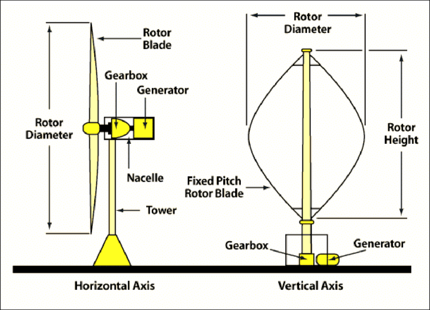
Figure 1: Horizontal and Vetical Axis Wind Turbines (Thrailkill, 2018)
Design Considerations
The design has been focussed around the H-Type Darrieus VAWT. This decision was made due to the linear blades making the design simpler and more cost efficient to manufacture. Taking the H-Darrieus (Figure 2) type VAWT as a base for redesign, a telescopic tower has been implemented so that the turbine can be extended and retracted. To suit this retractable blades have been designed that are fixed at full extension and under constant low tension to avoid entanglement when deploying or retracting the tower.

Figure 2: Various VAWT Example Designs (Castellani et al., 2019)
The Development Process
As part of the development process, new ideas and potential designs were speculated. As a result of this, a number of significant design limitations became apparent. The main one is that the traditional H-type turbines use a blade shape that generates both lift and drag (Figure 3). This design is generally much more energy efficient and supports higher rotational velocities. However, due to the complex shape of the blades, it would be very difficult to make them retractable in a cost effective way. Therefore the blades were made of a constant thickness and turned through 90o so that they would rely on drag alone to generate the rotation.

Figure 3: H-type Darrieus Blade Cross Section (Mohamed et al., 2020)
The Prototype
As part of the research conducted in this project, a prototype was designed and assembled to assess functionality. The prototype is much smaller than what it could due to the availability of parts, therefore the function of the protoype is exponentially less than what it would be on alarger scale. All design work was completed on Autodesk Fusion360 (Figure 4). The parts for the prototype were then 3D printed out of PLA using an FDM printer (Figure 5). Other components were bought and modified to extract the useful parts. These include:
- 1 x Car power antenna
- 4 x 2m Belt stanchions
- 2 x Bearings to suit shafts
- 1 x 12v DC motor
- 1 x Pulley belt to suit motor
Figure 4: CAD Assembly of Turbine (Milburn, 2022)
Future Opportunities
As the project is still underway, no results have yet been generated. However, if the project proves to be a viable means of generating clean energy, it could be deployed in a number of different ways. One way would be to integrate the turbine into urban environments such as roof tops or tiles. A small amount of product development could lead to a system capable of remote deployment or retraction giving the consumer complete control over turbione functionality as well as reducing the safety risks and costs of mainenance. This type of turbine can also be installed as part of an array of similiar turbines to achieve a large amount of power generation within a relatively small space
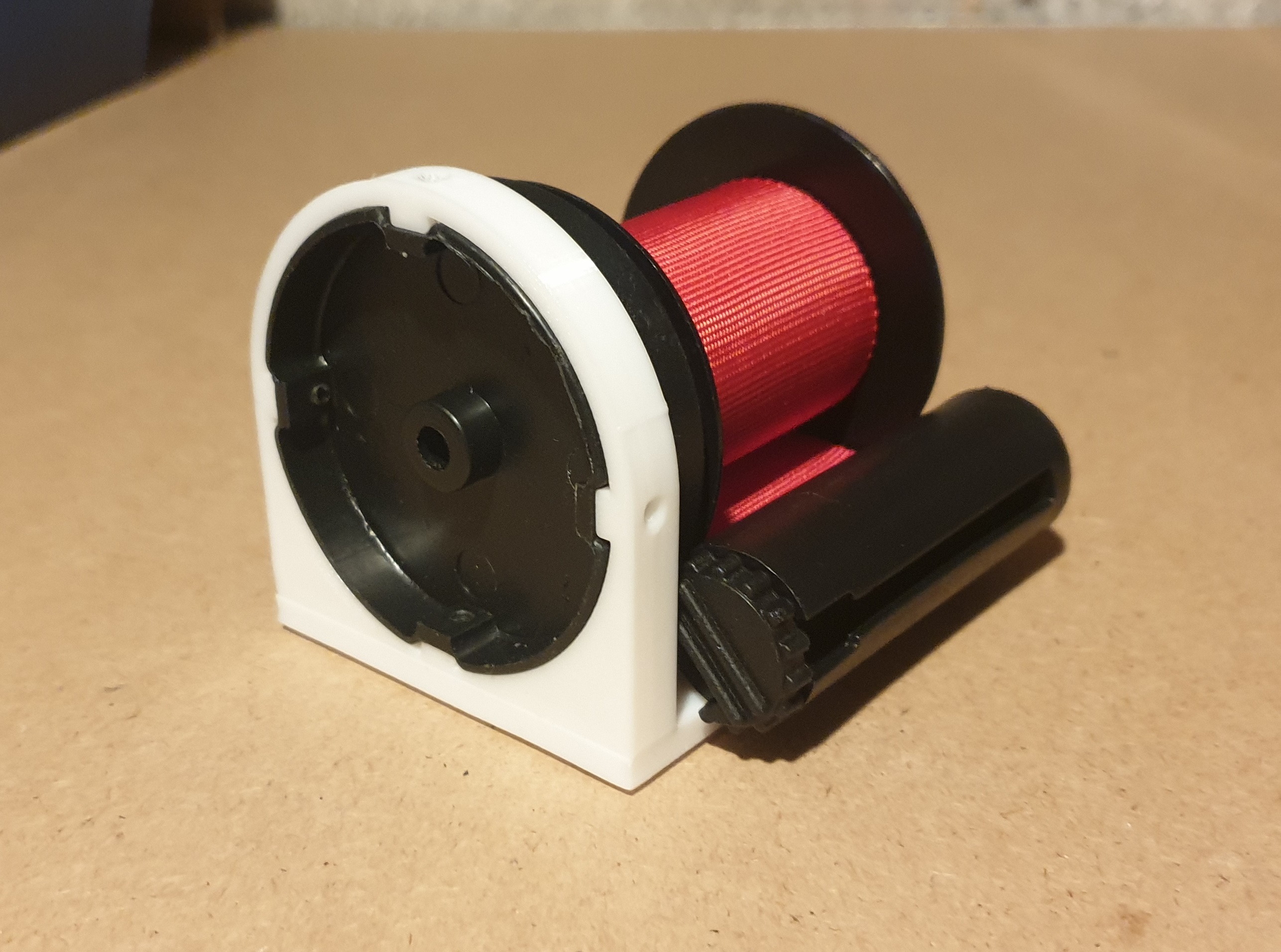
Figure 5: 3D Printed Blade Holder (Milburn, 2022)
References
Figure 1: Thrailkill, M., 2018. Horizontal and Vertical Axis Wind Turbines. [image] Available at: <http://www.windturbineworks.com> [Accessed 21 February 2022].
Figure 2: Castellani, F., Astolfi, D., Peppoloni, M., Natili, F., Buttà, D. and Hirschl, A., 2019. Experimental vibration analysis of a small scale vertical wind energy system for residential use. Machines, 7(2), p.35. Various VAWT Example Designs. [image]
Figure 3: Mohamed, O., Ibrahim, A., Etman, A., Abdelfatah, A. and Elbaz, A., 2020. Numerical investigation of Darrieus wind turbine with slotted airfoil blades. Energy Conversion and Management: X, 5, p.100026. H-type Darrieus Blade Cross Section. [image]
Figure 4: Milburn, M., 2022. CAD Assembly of Turbine [image]
Figure 5: Milburn, M., 2022. 3D Printed Blade Holder [image]
Slide 1 image (max 2mb)
Slide 1 video (YouTube/Vimeo embed code)
Image 1 Caption
Slide 2 image (max 2mb)
Slide 2 video (YouTube/Vimeo embed code)
Image 2 Caption
Slide 3 image (max 2mb)
Slide 3 video (YouTube/Vimeo embed code)
Image 3 Caption
Slide 4 image (max 2mb)
Slide 4 video (YouTube/Vimeo embed code)
Image 4 Caption
Slide 5 image (max 2mb)
Slide 5 video (YouTube/Vimeo embed code)
Image 5 Caption
Slide 6 image (max 2mb)
Slide 6 video (YouTube/Vimeo embed code)
Image 6 Caption
Slide 7 image (max 2mb)
Slide 7 video (YouTube/Vimeo embed code)
Image 7 Caption
Slide 8 image (max 2mb)
Slide 8 video (YouTube/Vimeo embed code)
Image 8 Caption
Slide 9 image (max 2mb)
Slide 9 video (YouTube/Vimeo embed code)
Image 9 Caption
Slide 10 image (max 2mb)
Slide 20 video (YouTube/Vimeo embed code)
Image 10 Caption
Caption font
Text
Image (max size: 2mb)
Or drag a symbol into the upload area















Image description/alt-tag
Image caption
Image link
Rollover Image (max size: 2mb)
Or drag a symbol into the upload area


Border colour
Rotate
Skew (x-axis)
Skew (y-axis)
Image (max size: 2mb)
Or drag a symbol into the upload area


Image description/alt-tag
Image caption
Image link
Rollover Image (max size: 2mb)
Or drag a symbol into the upload area


Border colour
Rotate
Skew (x-axis)
Skew (y-axis)
Image (max size: 2mb)
Or drag a symbol into the upload area


Image description/alt-tag
Image caption
Image link
Rollover Image (max size: 2mb)
Or drag a symbol into the upload area


Border colour
Rotate
Skew (x-axis)
Skew (y-axis)
Image (max size: 2mb)
Or drag a symbol into the upload area


Image description/alt-tag
Image caption
Image link
Rollover Image (max size: 2mb)
Or drag a symbol into the upload area


Border colour
Rotate
Skew (x-axis)
Skew (y-axis)
Image (max size: 2mb)
Or drag a symbol into the upload area


Image description/alt-tag
Image caption
Image link
Rollover Image (max size: 2mb)
Or drag a symbol into the upload area


Border colour
Rotate
Skew (x-axis)
Skew (y-axis)
Image (max size: 2mb)
Or drag a symbol into the upload area


Image description/alt-tag
Image caption
Image link
Rollover Image (max size: 2mb)
Or drag a symbol into the upload area


Border colour
Rotate
Skew (x-axis)
Skew (y-axis)