Liam Winder
The demand for ultra-low and zero emissions in urban areas to improve air quality is at an all-time high. Manufacturers must act in developing their electric powertrain products in time to aim to be market leaders with new technology. The key challenges that arise with this technology are focused on the safe installation of these systems. The electrical architecture must be robust enough to ensure the system remains safe in all vehicle applications as well as in changeable weather conditions. The routing of the cabling is considered a key element of the design to ensure the safest and most cost-effective solution is adopted.
In battery electric vehicles, the criticality of the harness strategy is vital in the overall safety and equal wear of the Rechargeable Energy Storage System (R.E.S.S). This paper analyses the effects of High Voltage Impedance on Low Voltage Systems. It also considers the key factors in designing and routing High Voltage (HV), Alternating Current (AC) & Direct Current (DC) cabling in Medium Duty Trucks. Cable specific software was used to design the harnesses. These designs are imported into a fully representative vehicle within Computer Aided Design (CAD) software. Using a variety of cable manufacturers, the possible imbalance to the R.E.S.S units was calculated and used to develop the system further and conclude the findings.

Liam Winder
Many manufacturers are pushing forward to get a vehicle to the market, but are the dangers of High Voltage truly understood?
No formalised standard is currently constructed regarding the safe handling and installation of these cables. This thesis identifies a real-world application whereby currently, there is limited research.
Each system needs analysing fully to ensure the optimum cable is selected. Some systems require the use of multicore cables (typically lower current systems). Whereas, the majority of the others require a single core cable for each line.
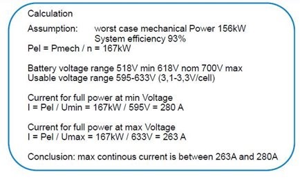
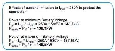
Along with the power requirements of the cable, the same considerations are essential for the designated connector. One example, is connectors can limit circuit performance due to their current carrying capacity values. An example of this could be the powertrain system. This typically will be the system with the greatest demand in both current and voltage. Consequently, producing more heat.
Heat characteristics offer another variable to be considered. Heat is carried through harnesses and too short of a run can lead copper failure in the wire. As a result, some instances require a minimum run length to dissipate the heat.
Every cable has something known as its bend radius. The bend radius stipulates the tightest the internal curve of any given bend can be before there is risk of damaging any part of the conductor. This damage can be caused by bend stress or a build-up of heat energy. Any form of damage to the harness increases susceptibility to electromagnetic interference or risk of exposed High Voltage.
All significant mechanical systems are designed, configured and refined through the use of Computer Aided Design (CAD) systems. Historically, electrical cabling tends to fall short in this aspect. This is due to many factors, including complexity and it being a none value added exercise.
However, with the turn of Electric Vehicles, cable size has replaced fuel pipes. The footprint, mass properties and installation requirements mean they can no longer be overshadowed by other systems in a vehicle’s configuration.
Factors to consider are:
Not route too close to Low Voltage cables to mitigate the potential of Electric ‘noise’ to low voltage systems.
Route cables with opposing current flow next to each other.
Support for the weight of the cables.
Securement of the cables.
Cable specific bend radiuses.
The next level of the development is to lay the cables into a physical vehicle. The design in CAD was utilised as an installation guide.
The key challenge faced when installing the system is the rigidity of the cables.
Due to the construction of the cable having multiple core layers, it proved challenging to ensure the cables were installed smoothly.
A factor of this is the securement of the cables at multiple sections of a bend. This is to ensure any bend does not kink further down the line, nor push the cable out to cause a foul condition further down the run. These differences between real world installation and a CAD installation occur due to the physical flexibility of a cable.
Nonetheless, the opportunity was presented to view a current competitors EV. I took great interest in how other Engineers tackled the challenge of routing a High Voltage architecture. Below identifies a comparison between the product I designed and a competitor’s installation.


